Synopsis by Dave Perkins: Have you ever been frustrated while working on a set because you couldn’t tell if an IF transformer coil was OK or shorted since the resistance readings for the two conditions is almost the same? Here is an excellent tech write up on building and using a fairly simple tester that club member Rob Tracy put together and gave to each of those attending the last club meeting. This is the kind of weekend project that makes your troubleshooting more trouble free and is something that is a valuable addition to your test bench. You don’t even need to use a printed circuit board, this could be built on a piece of perf board.
The Coil Tester
by Rob Tracy
Measure inductance and resonant frequency
How do you test a coil? Usually, you want to know two things: the inductance and the frequency at which it will resonate with a particular capacitor. This handy tester helps you find both. Connect it to any LC tuned circuit, and it oscillates at the resonant frequency, from below 20 kHz to above 20 MHz. What’s more, at the flip of a switch, you can use the built-in 150 pF capacitor to make a tuned circuit out of any coil and deduce the inductance from the frequency at which it resonates.
You can read the frequency on a frequency counter, calibrated oscilloscope, grid dip meter, or communications receiver. From the frequency, you can find the inductance with the accompanying nomograph or computer program. The tester works with coils over a million-to-one inductance range from 0.2 µH to 0.2 H or more.
The Search for the Circuit
For years I had been looking for an oscillator controlled by a single parallel tuned circuit. The Hartley and Colpitts circuits won’t do because they require, respectively, a tapped coil and a “tapped” (double) capacitor. The Clapp circuit uses a single coil and capacitor, but they’re in series. That’s not good enough. I wanted an oscillator that would take a parallel tuned circuit so I could measure the resonant frequencies of IF transformers and other ready-made tuned circuits. Also, every coil has a self-resonant frequency at which it is parallel-resonant with its own internal capacitance; only a parallel-tuned oscillator will test this directly.
Figure 1. C1 and Lx control the frequency of this source-coupled FET oscillator. S1 removes C1 from the circuit to enable testing of tuned circuits or self-resonant coils.
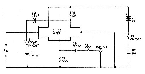 The circuit in Figure 1 does the job. It’s adapted from a cathode-coupled oscillator described by F.C. Alexander, Jr. in the September 1946 issue of QST, pages 69-70, who credits it to F. Butler. Mr. Alexander reported that the oscillator would really take abuse; he found it would still oscillate at 10 MHz with a 6J6 tube with four volts on the filament and a mere 3 volts (instead of the usual 300) for the plate supply. The FET version was first described by L.F. Heller in Wireless World, September 1969, page 409, but he used an RF choke instead of my resistor R1.
Understanding the Circuit
Think of Q1 as a source follower and Q2 as a common-gate amplifier. The two stages communicate by sharing source resistor R2. Positive feedback goes through C2, and the tuned circuit ensures that the feedback is only effective at the resonant frequency.
The high supply voltage (18 volts) helps extend the frequency range and improves the performance with low-Q tuned circuits. The oscillator won’t work with a crystal, but it will sometimes oscillate with a resistor in place of the coil.
The output, rich in harmonics, is taken across R2 (Photo A). R3 provides some output isolation; without it, a capacitive load-such as the internal capacitance of a long cable-could sometimes stop the oscillation.
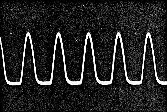 Photo A. The output waveform consists of half-sine-waves and is rich in harmonics.
Construction
I built the oscillator on perfboard and housed it in a Radio Shack instrument case. The layout is not critical as long as all leads are kept short. Even the test leads should be short-just long enough to reach out of the enclosure-because their inductance is part of the tuned circuit.
Switch S1 is also part of the tuned circuit; to save lead length, I mounted it through a hole in the circuit board, and the switch itself attaches the circuit board to the front panel (Figure 2). The batteries are held by clips mounted on the back panel (Photo D); the clips are lined with vinyl tape to keep the batteries from slipping out.
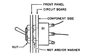 Figure 2. To keep leads short, SI mounts in a hole in the circuit board.
Measuring Resonant Frequency
The simplest way to read out the frequency of oscillation is to use a frequency counter. Make sure the reading is stable and is the same with the counter set on more than one range. You can also measure frequency with a calibrated oscilloscope:
Frequency (MHz) = 1 / Length of one cycle (microseconds)
Don’t strive for great accuracy; because of stray capacitances and inductances, your results are bound to be off by a few percent.
You can also determine the frequency by tuning in the oscillator on a communications receiver. No physical connection is needed; just place the receiver close to the coil and look for an unmodulated carrier. When you find it, also try one-half, one-third, and one-fifth of that frequency to determine whether you initially heard a harmonic.
Or you can use the ham’s traditional tool, a grid dip meter. To do this, start up the test oscillator, then use the dip meter as a field strength indicator. That is, set its gain so that it does not oscillate, and place its coil right next to the coil under test. Tune across the band until you get a slight but sharp peak in the meter reading. This is more accurate and more sensitive than testing a tuned circuit with the dip meter by itself.
What’s the Inductance?
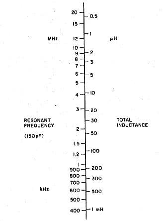 Figure 3. Nomograph to find inductance of a small coil from a single frequency reading. Inductances up to 0.1 H can be measured by taking two readings (with and without the 150 pF capacitor) and doing calculation.
To find the inductance of a small RF coil, measure the frequency of oscillation with C1 in the circuit. You can then find the inductance with the nomograph in Figure 3. In fact, you may want to stick a copy of the nomograph to the top of the test oscillator.
The nomograph works as long as you’re dealing with a coil whose internally distributed capacitance is small. Any coil with more than 50 turns is likely to have appreciable distributed capacitance. Fortunately, you have an easy way of measuring this, too-just read the resonant frequency with C1 out of the circuit as well as in it. Then use the BASIC computer program in Figure 4 to do the calculations, or work through the formulas from the program on your calculator.
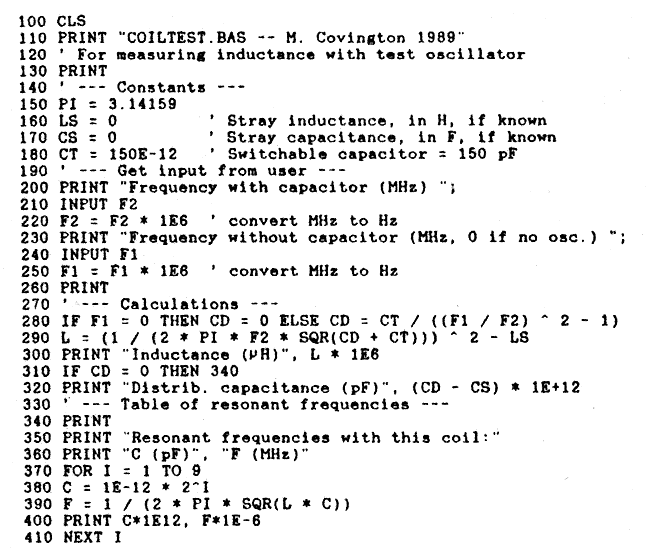 Figure 4. This program finds inductance and distributed capacitance from frequency measurements. It was developed on an IBM PC but should run in practically any version of BASIC.
The program was written on an IBM PC but should run in practically any version of BASIC. It finds the inductance and distributed capacitance, then prints a table of resonant frequencies and the capacitances needed to obtain them (Figure 5). That’s helpful because usually, hams don’t really want to know inductance for its own sake; they want to make a resonant circuit for a particular frequency.
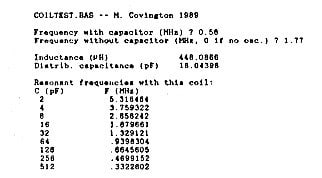 Figure 5. Sample output from the computer program. These data are from a coil labeled 470 µH, 5%.
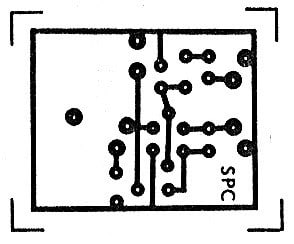 Figure 6. Foil diagram.
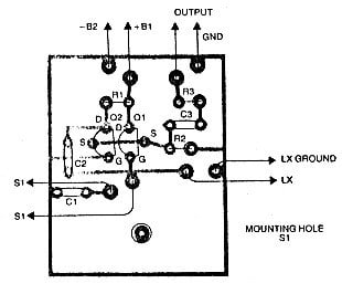 Figure 7. Parts placement.
If you test an IF transformer, you’ll get an inductance and a distributed capacitance that includes the built-in capacitor. For instance, a 10.7 MHz IF transformer that I tested came out as 3.6 µH in parallel with 60 pF, and according to the table displayed by the program, it will tune 40 meters if I add slightly more than 128 pF.
Improving Accuracy
You’ll notice that the program has variables for the stray inductance (LS) and stray capacitance (LC) of your setup, in henries and farads respectively. In the program as shown, they are set to zero, but you can gain additional accuracy by measuring or estimating them and putting them into the program.
Stray capacitance is hard to measure and is fairly unimportant, since the 150 pF capacitor completely swamps it. As a ballpark estimate, try 1 pF, which you would enter into the program as CS = 1E -12 (i.e., 1 × 10-12 farads).
Stray inductance is more important. It’s likely to be about 0.2 pH. To measure it, wind three or four turns of solid hookup wire into a small coil, then measure the resonant frequency with C1 in the circuit. You’ll probably get something like 20 MHz. Now spread out or unwind the coil to make the frequency rise. You’ll get a maximum frequency around 25 MHz before oscillation stops. Put this frequency into the computer program, and you’ll get back a fair approximation to the stray inductance of your setup. Now modify the computer program to make this number the value of LS (for example, if it’s 0.2 µH, make LS = 0.2E-6).
By the way, this is not the highest frequency at which you’ll ever see oscillation. A high Q tuned circuit can override the low Q stray inductance and make the oscillator run as high as 120 MHz.
An Essential Tool
Two weeks ago I didn’t know an oscillator like this could be built. Now I don’t know how I’d get along without it. The ability to measure inductance and resonant frequency is so fundamental to RF circuit design that an instrument like this belongs in every ham shack.
Parts list
| B1, 2 |
9V |
| C1 |
150 pF 5% |
| C2 |
33 pF |
| C3 |
47 nF |
| Q1, 2 |
J310 FET |
| R1 |
10 kΩ |
| R2 |
1 kΩ |
| R3 |
1 kΩ |
Courtesy of N4TMI, Michael A. Covington and
http://www.robkalmeijer.nl/techniek/electronica/radiotechniek/hambladen/73/1990/09/page48/index.html
Schematic updates to J310 FET by Rob Tracy
Article submitted/authored by Rob Tracy
WordPress editing Doug Spyrison
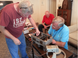
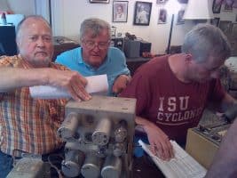
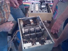
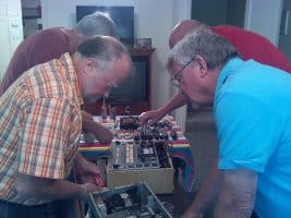
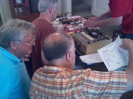
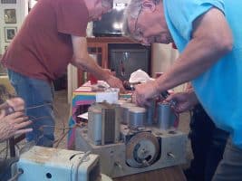
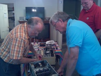 On Saturday June 10, 2017 a club meeting was held at the home of Rob Tracy in Des Moines. Due to schedule conflicts, it was a small gathering. In attendance were Rob, Al Bailey, Craig Huseboe, Dave Perkins and new member Ron Russel.